![]()
Free Nokia 4A0-205 Exam Questions and Answer from Training Expert Exam4Docs
Top Nokia 4A0-205 Courses Online
One of the key areas covered by the Nokia 4A0-205 exam is the fundamentals of optical networking. This includes topics such as optical transmission systems, optical network design, and optical network management. 4A0-205 exam also covers advanced topics such as wavelength division multiplexing (WDM) and optical switching.
Nokia 4A0-205 exam is an important certification for professionals who want to demonstrate their knowledge and expertise in optical networking. Nokia Optical Networking Fundamentals certification test is recognized worldwide and is an essential credential for individuals seeking career advancement in the telecommunications industry. A successful completion of the exam demonstrates that an individual has the necessary skills and knowledge to design, install, and maintain optical networks. Furthermore, the Nokia Optical Networking Fundamentals certification provides individuals with a competitive advantage in the job market as it demonstrates their commitment to self-improvement and professional development.
NEW QUESTION # 27
What is the function of the express channel interface?
- A. It enables the high speed route for all channels terminated in the local node.
- B. It passes all the channels not terminated in the local node through the downstream node.
- C. It drops high capacity channels in the local node.
- D. It enables the high speed route for all channels passing through that interface.
Answer: B
Explanation:
Comprehensive and Detailed Explanation From Nokia Optical Networking Fundamentals:
In the context of WDM (Wavelength Division Multiplexing) node architecture, an express channel interface (often associated with OADMs or ROADMs) is specifically designed to handle "through" traffic. In a multi-node optical network, not every wavelength (channel) needs to be processed or terminated at every site it passes. To maintain signal integrity and reduce latency, these wavelengths are kept in the optical domain.
The express interface allows these optical channels-those not terminated or "dropped" at the local node-to bypass the local transponders and multiplexers, flowing directly to the downstream node. This photonic bypass avoids unnecessary O-E-O (Optical-Electrical-Optical) conversions, which would otherwise require expensive hardware and increase power consumption. By utilizing express paths, the Nokia 1830 PSS can scale to support massive core network capacities while ensuring that only the relevant traffic is diverted to the local client-facing ports.
NEW QUESTION # 28
What is the purpose of the NFM-T deploy menu?
- A. It is used to deploy new operators (administrator, observers, and so on) to access the platform.
- B. It is used to deploy additional shelves to existing SWDM nodes.
- C. It is used to create new network instances, such as physical connections, infrastructures and services.
- D. It is used to import EPT files to deploy the network based on the EPT design.
Answer: C
Explanation:
The NFM-T (Network Functions Manager - Transport), now part of the WaveSuite Network Operations Center (WS-NOC), is the centralized management system for Nokia's optical portfolio. The Deploy menu is the primary engine for operationalizing the network. Its fundamental purpose is to create and provision new network instances, which encompasses the lifecycle of the transport infrastructure.
Specifically, this menu allows operators to establish physical connections (fiber links between nodes), build out the infrastructure (defining the topology and node roles), and most importantly, provision services (such as ODUk or Optical Channel services). While the EPT (now WaveSuite Planner) designs the network, and those files can be used as a reference, the actual "birth" of a service in the live network-mapping it from the source transponder to the destination through the required ROADM degrees-is executed via the Deploy menu. It translates the high-level intent into specific cross-connect commands sent to the individual Network Elements (NEs), ensuring that the underlying hardware is correctly configured to carry client traffic.
NEW QUESTION # 29
Where can the user set the long-haul WT decoder parameter, when designing a network with EPT?
- A. In the optimization parameters
- B. In the network parameters
- C. In the audit menu
- D. In the NE parameters
Answer: D
Explanation:
The long-haul WT decoder parameter can be set in the NE parameters when designing a network with EPT. This parameter is used to adjust the sensitivity of the decoder and can help to improve the accuracy of the measurements for long-haul WTs.
The Network Element (NE) parameters in EPT (Element Planning Tool) are used to configure various settings and options for the network elements in the network. The long-haul WT decoder parameter is one such setting that can be configured in the NE parameters section. The user can access the NE parameters by navigating to the NE Parameters menu within the EPT interface. The user can then select the appropriate network element and modify the settings as needed. This information can be found in the Nokia guide for EPT.
NEW QUESTION # 30
What does it take to get connected to the NSP platform?
- A. A browser and the NSP IP address. Then, a browser plugin needs to be installed and the laptop rebooted before the NSP can be correctly reached.
- B. The NSP package should be downloaded from the Nokia website and properly licensed for the specific workstation to be used.
- C. A browser and the NSP IP address; and from the landing page, the NSP application should be downloaded and launched.
- D. A browser, the NSP IP address, and the credentials to access the web-based interface (WebUI).
Answer: D
Explanation:
To get connected to the Nokia Service Platform (NSP) platform, you need a browser and the NSP IP address. Then, you need the credentials to access the web-based interface (WebUI) for the NSP platform. Once you have these, you can access the NSP platform from a web browser.
NEW QUESTION # 31
Is it possible to modify node parameters within the edit EPT menu?
- A. Yes, the user can apply manual changes directly from this view
- B. No, this view is used to display a close-up view of the node
- C. Yes, the user can apply manual changes but only for non-GMPLS nodes, as the control plane reserves node resources not editable by the user
- D. Yes, but the user can modify only the node name and location
Answer: C
Explanation:
Yes, the user can apply manual changes but only for non-GMPLS nodes, as the control plane reserves node resources not editable by the user. The edit EPT menu allows the user to view information about a node but is not used to modify node parameters. The user can only apply manual changes to non-GMPLS nodes, as the control plane reserves node resources which cannot be modified by the user.
NEW QUESTION # 32
How are the EPT systems related to NFM-T when CPB is performed?
- A. The systems are displayed on the CPB panel and they can be individually selected
- B. The systems are displayed on the CPB panel, however they cannot be individually selected as they need to run all together
- C. The systems are not reported on CPB, but only through the Equipment Manager
- D. The systems are not reported on CPB, as this Is transparent to the user and the whole network is validated and provisioned in one step
Answer: A
Explanation:
The EPT systems are displayed on the CPB (Commissioning Parameter Builder) panel and they can be individually selected. This allows the user to configure the network elements in the network and provision them according to their specific requirements. The systems are not reported on CPB, but through the Equipment Manager. The Equipment Manager is the interface used to configure the network elements and the EPT systems. The NFM-T is not related to the CPB and does not affect the CPB process.
NEW QUESTION # 33
What is the block that converts the colorless (or black and white) client signal to a specific optical channel in a WDM system?
- A. Dispersion compensation module (DCM)
- B. Wavelength router (WR)
- C. Optical transponder (OT)
- D. Static filter device (SFD)
Answer: C
Explanation:
Comprehensive and Detailed Explanation From Nokia Optical Networking Fundamentals:
The Optical Transponder (OT) is the essential interface component in a WDM system that bridges the gap between the client-side equipment and the WDM line-side. Client signals, often referred to as "colorless" or "black and white" because they typically use standard 1310nm or 1550nm short-reach optics, cannot be directly multiplexed into a DWDM fiber because they would interfere with one another.
The Transponder performs an O-E-O (Optical-Electrical-Optical) conversion process: it receives the client's optical signal, converts it to an electrical format to perform 3R functions (Re-amplification, Re-shaping, and Re-timing) and often wraps it into an OTN (Optical Transport Network) frame, and then re-transmits it using a high-precision, ITU-T grid-compliant colored wavelength. In the Nokia 1830 PSS portfolio, these can be dedicated transponders for a single high-speed service or Muxponders, which aggregate multiple lower-speed client signals into a single high-speed "colored" line interface. Other components like the SFD are used for multiplexing those colors, and the DCM is used for managing fiber impairments, but only the Transponder performs the initial frequency conversion.
NEW QUESTION # 34
What is the meaning of first, second, and third window in the optical fiber propagation context?
- A. These windows correspond to three different minimum and maximum optical power levels used for optical transmission.
- B. Different optical transmission windows correspond to different safety requirements and rules for the related lasers operating with these windows.
- C. These three windows are three different angles of incidence of the light injected by the laser into the fiber.
- D. These windows are three different wavelength intervals where the WDM optical transmission occurs.
Answer: D
Explanation:
In optical fiber propagation context, the first, second, and third window refer to different wavelength intervals where the WDM (Wavelength Division Multiplexing) optical transmission occurs.
The first window is the lowest loss window and is typically in the range of 1300-1324nm. This is the most commonly used window for long-haul communications.
The second window is the 1550 nm window and is the most widely used window for long-haul and ultra-long-haul communications. This window has a lower attenuation than the first window, but it also has more dispersion, which can limit the maximum transmission distance.
The third window is the range of 1625-1675 nm, it is also called the L-band window. This window has lower attenuation than the first and second window but its usage is limited due to the high cost of equipment and lack of commercial devices.
These windows are used in WDM systems to increase the capacity of the fiber by transmitting multiple channels of data at different wavelengths on the same fiber.
A,C,D are not correct as they are not related to the meaning of first, second, and third window in the optical fiber propagation context.
Reference:
Nokia Optical Networking Fundamentals, Nokia Press (ISBN:978-1-4822-8109-4)
https://www.nokia.com/networks/solutions/optical-networking/
https://en.wikipedia.org/wiki/Wavelength-division_multiplexing
NEW QUESTION # 35
How does a Raman pump work in the 1830 specific implementation?
- A. The amplification is done simultaneously for all channels as they enter the board.
- B. As the incoming signal power increase, the gain of the amplifier is reduced.
- C. The pump light travels in the opposite direction of the signal to be amplified, amplifying it while it arrives from the adjacent node.
- D. The pump light travels in the same direction of the signal, amplifying it while it flows in the fiber towards the following node.
Answer: C
Explanation:
In Raman amplification, a pump laser is used to excite the Raman-active molecules in the fiber, which then amplifies the signal light as it travels in the opposite direction. In the 1830 specific implementation, the pump laser is typically a high-power laser that is launched into the fiber in the opposite direction to the signal. The pump light interacts with the Raman-active molecules in the fiber, which then amplifies the signal light as it travels in the opposite direction. This allows the Raman pump to provide a gain that increases with distance, which can be used to compensate for the loss of signal power as it travels through the fiber.
NEW QUESTION # 36
WDM allows transmission systems to:
- A. Transport multiple signals transparently, onto several wavelengths, all together over one single fiber
- B. Share a single signal among multiple fibers doing load balancing, and thus increasing the reliability of the optical transmission
- C. Allocate different signals to different time slots
- D. Increase the bit rate of each client signal by spreading it over multiple wavelengths
Answer: A
NEW QUESTION # 37
What is an optical switch?
- A. A device that selectively transfers an optical ODU frame from one port to another.
- B. A device that selectively transfers an optical signal from one port to another.
- C. A device that converts optical signal to electrical to allow switching through the electrical matrix, and then again to optical towards the next card (and versa).
- D. A device that groups multiple lambdas in one multiplexed signal.
Answer: B
Explanation:
Comprehensive and Detailed Explanation From Nokia Optical Networking Fundamentals:
In the context of optical networking fundamentals, an optical switch (often referred to as a Photonic Switch or Layer 0 switch) is defined as a device that routes an optical signal-composed of photons-from an input port to one or more output ports without converting it into an electrical signal. This process is known as transparent switching. It operates entirely within the optical domain, maintaining the integrity of the lightwave regardless of the data rate or protocol being carried (e.g., SDH, Ethernet, or OTN).
It is important to distinguish this from Option D, which describes an Electrical or ODU Switch (Layer 1). In a device like the Nokia 1830 PSS-24x, signals are converted to electrical format (O-E-O) to be switched at the ODU (Optical Data Unit) level via a central fabric. While this provides "any-to-any" grooming, a true optical switch (like a WSS found in ROADMs) simply steers the light. The primary advantage of an optical switch is its ability to handle massive amounts of bandwidth with extremely low latency and lower power consumption compared to electrical switching, as it avoids the overhead of repeated O-E-O conversions at intermediate network nodes.
NEW QUESTION # 38
Which statement is correct about node synchronization?
- A. Full synchronization retrieves all items from the node (NE parameters. Ports, Alarms, Internal Links, etc)
- B. Node synchronization is executed to test the reachability of a node
- C. Full synchronization retrieves the correlated alarms from the node
- D. Node synchronization is executed to align the time of the node to the time of the NFM-T platform
Answer: A
Explanation:
Node synchronization is a process of keeping the NFM-T database in sync with the nodes in the network. The synchronization process will download all the items from the node, including NE parameters, ports, alarms, internal links, etc., to the NFM-T database. This ensures that the NFM-T database is up to date and the network is running efficiently.
NEW QUESTION # 39
Which of the following are the main reasons for fiber attenuation?
- A. Chromatic dispersion (CD) and polarization mode dispersion
- B. Scattering and absorption
- C. Refraction and reflection
- D. Small channel spacing
Answer: B
Explanation:
Scattering and absorption are the main reasons for fiber attenuation. Scattering occurs when light bounces off the sides of the fiber, while absorption happens when light is absorbed by the glass or other materials that make up the fiber. Chromatic dispersion (CD) and polarization mode dispersion (PMD) are also factors that can cause attenuation, but they are not the main causes. Small channel spacing can also cause attenuation, but it is a secondary factor and is only significant in certain cases.
NEW QUESTION # 40
How is it possible to check the activation status of GMRE on a node?
- A. The GMRE activation status is reported in the supervision state column on the node list
- B. The ControlPlane status column on the node list displays the GMRE status for the selected node
- C. The GMRE reachability can be tested via ping request from NFM-T
- D. The GMRE activation status is reflected on the color of the icon representing the node
Answer: A
Explanation:
The GMRE activation status is reported in the supervision state column on the node list. The supervision state column displays the GMRE status of the node, which is either "Activated" or "Not Activated". This allows the user to quickly check the GMRE activation status of a node without having to ping the node from the NFM-T platform.
NEW QUESTION # 41
With reference to the image, where is the OPS card placed to provide the OMSP protection?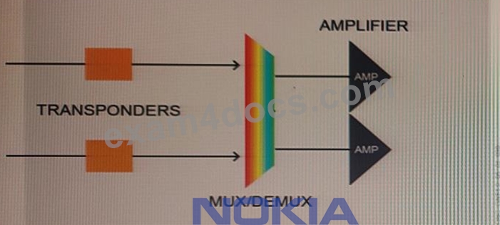
- A. Between the mux/demux and the amplifier
- B. After the amplifiers
- C. Between the transponders and the mux/demux
- D. Before the transponder, on the client side, towards the external device
Answer: D
NEW QUESTION # 42
By using the EPT run design command, are the previously designed elements removed?
- A. Yes, they are but only the first time the command is launched as - for future design phases - the existing packs need to keep the same slotting.
- B. Yes, although this is not happening in case of GMPLS-enabled nodes because existing slots cannot change as they are controlled by another manager (GMRE).
- C. It depends, the user is prompted to choose whether to delete or leave the previously designed elements.
- D. Not the design is always progressive, on top of the previous design.
Answer: C
Explanation:
The EPT run design command can remove previously designed elements, but the user is prompted to choose whether to delete them or leave them intact. This allows the user to progress their design while still keeping the existing elements in place. If the user selects to leave the existing elements, then they will remain in the same slots. If GMPLS nodes are used, the existing slots cannot change as they are controlled by another manager (GMRE).
NEW QUESTION # 43
Which of the following statements about Wavelength Tracker monitoring points in CDC-F architecture is TRUE?
- A. Wavelength Tracker monitoring points are settled on IRDMxx line interfaces only.
- B. Wavelength Tracker monitoring points are settled on IRDMxx line interfaces and on CWR CLS interfaces.
- C. Wavelength Tracker monitoring points are settled on ITL mux interfaces and on OTs line interfaces.
- D. Wavelength Tracker monitoring points are settled on IRDMxx and OTs line interfaces.
Answer: B
Explanation:
Comprehensive and Detailed Explanation From Nokia Optical Networking Fundamentals:
In a CDC-F (Colorless, Directionless, Contentionless, Flex-grid) architecture, the placement of monitoring points is vital for end-to-end visibility of wavelengths. Nokia's Wavelength Tracker technology relies on these points to detect the unique "keys" or signatures associated with each wavelength. In a CDC-F node, the primary monitoring points are located on the IRDMxx (Intelligent Reconfigurable Demultiplexer/Mux) line interfaces and the CWR (Colorless Wavelength Router) CLS (Colorless) interfaces.
The IRDM monitoring points allow the system to verify the power and presence of wavelengths as they enter or leave the fiber spans (degrees). The CWR CLS monitoring points are critical because they provide visibility at the "Colorless" add/drop stage. By having monitoring at both locations, the WaveSuite Network Operations Center (WS-NOC) can pinpoint exactly where a signal loss or power degradation is occurring-whether it's in the external fiber plant or within the internal colorless switching fabric of the ROADM. This granular visibility is what allows Nokia's "Power Management" to automate balancing across complex mesh topologies.
NEW QUESTION # 44
What is the purpose of the validate step in the EPT design process?
- A. This step is optional and is useful to verify the network element layout before going through the commission step.
- B. During this step, the run design action is triggered for network design consistency check and errors fixing.
- C. During this step, the configuration available on the involved network elements is compared with the design provided by EPT.
- D. This step is used to measure optical power performances over an existing network before making changes.
Answer: B
Explanation:
The validate step in the EPT design process is used to trigger the run design action, which is responsible for verifying the consistency of the network design and fixing any errors that may exist. During the validation process, the system will compare the configuration available on the involved network elements and the design provided by EPT, and any discrepancies will be flagged for further investigation or correction.
NEW QUESTION # 45
......
Nokia 4A0-205 exam covers a wide range of topics, including optical networking concepts, network design, installation and commissioning, and troubleshooting. Passing 4A0-205 exam demonstrates that an individual possesses the necessary knowledge and skills to design, deploy, and manage optical networks using Nokia's equipment. Nokia Optical Networking Fundamentals certification is highly valued in the telecommunications industry, and it can help individuals advance their careers and gain a competitive edge over their peers.
New (2026) Nokia 4A0-205 Exam Dumps: https://www.exam4docs.com/4A0-205-study-questions.html
4A0-205 Practice Dumps - Verified By Exam4Docs Updated 62 Questions: https://drive.google.com/open?id=1vdLHVNTKy3dOydXLe6bFRKM76mMhZgrx